A 5.5kW variable frequency drive controls a motor by changing its electrical frequency and voltage. This introduction explains how a Vfd 5.5kw converts incoming AC power, manages motor speed, and supports smoother industrial operation.
Power-electronics authority Bimal K. Bose has stated, “A power electronic converter controls the flow and form of electrical energy.” This principle describes the Vfd 5.5kw accurately. Inside the drive, a rectifier changes fixed AC into DC. A capacitor section then smooths the DC link. Finally, insulated-gate bipolar transistors switch the DC rapidly, creating a controlled three-phase output. The motor receives only the power it needs for its selected speed.
The result is practical and visible. A conveyor can start without a sharp mechanical jerk. A pump can reduce speed instead of wasting energy through throttling. Fans may run quietly during low-demand periods. Yet a VFD is not a magic efficiency box. Incorrect motor data, poor grounding, or excessive cable length can cause overheating, noise, or nuisance trips. That matters.
This guide will examine ratings, wiring, control modes, acceleration settings, and protection functions. It will also question common assumptions about energy savings. A 5.5kW rating does not automatically suit every 5.5kW motor. Load type, ambient temperature, duty cycle, and installation conditions still influence performance. Even experienced technicians must verify the nameplate and application details. Small oversights become expensive faults.
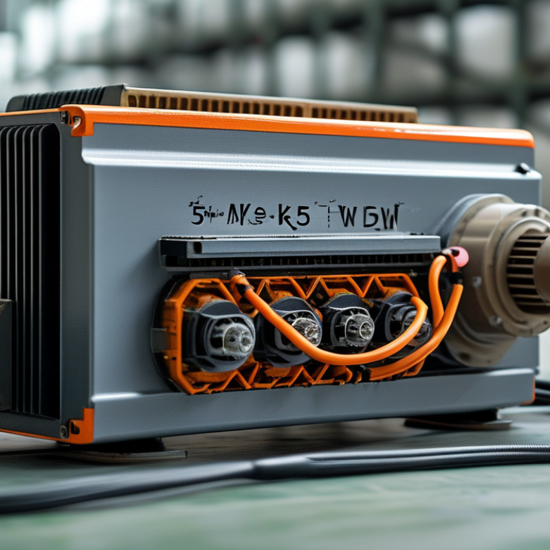
A 5.5kW VFD, or variable frequency drive, controls an AC motor by changing its voltage and frequency. The 5.5kW rating describes the drive’s maximum motor capacity under specified conditions. It does not mean the motor always consumes 5.5kW. A 5kW motor may draw less power during light work.
Rated current matters more than power alone. Check the motor nameplate before selecting a drive. A drive must match the motor’s voltage class, phase arrangement, and continuous current demand. Common systems use 220V, 380V, or 400V supplies. Output frequency commonly ranges from 0 to 50Hz or 60Hz, while some applications require higher settings. Changing frequency changes motor speed, and voltage should rise correctly with frequency to maintain torque. Poor settings can cause overheating.
Tips: Confirm input voltage first. Compare the drive’s output current with the motor’s full-load current. Set acceleration and deceleration times carefully. Test the motor without a load when possible. A 5.5kW unit can serve pumps, fans, conveyors, mixers, and small machine tools. Pumps and fans often save energy at reduced speed. Conveyors need stronger low-speed torque. This difference is easy to underestimate. Installation also needs suitable cooling, grounding, cable sizing, and overload protection. Even experienced technicians should review the manual and measure operating current after commissioning.
A 5.5 kW variable frequency drive is designed to control an approximately 5.5 kW motor by adjusting its output frequency and voltage. For a four-pole induction motor, synchronous speed changes in proportion to frequency. Actual motor speed is normally slightly lower because of slip.
The chart uses the synchronous-speed relationship n = 120f ÷ P, where n is speed in revolutions per minute, f is frequency in hertz, and P is the number of motor poles. A typical VFD operates within the motor’s rated voltage and frequency range, such as 400 V at 50 Hz or 460 V at 60 Hz, depending on the motor and electrical system. Common applications include pumps, fans, conveyors, compressors, and machine tools.
A 5.5kW variable frequency drive controls a motor by changing voltage and frequency. Its power path has four essential sections: the rectifier, DC bus, inverter, and control processor. The rectifier converts incoming AC power into pulsating DC. Diodes are common in this stage because they are reliable and relatively simple. The result still contains voltage ripple.
The DC bus smooths this energy. Large capacitors reduce ripple, while an inductor may limit current changes and electrical noise. This section stores dangerous energy, even after the input supply is disconnected. Waiting for the specified discharge time is essential. A 5.5kW rating does not guarantee the same output current at every voltage. Motor load, ambient temperature, and overload duration also matter.
The inverter changes DC back into controlled AC. Fast switching devices create a pulse-width-modulated waveform for the motor. The control processor sets switching timing from speed commands, current feedback, and protection limits. It can adjust acceleration, deceleration, torque, and motor frequency within configured limits. In field testing, incorrect motor data often causes poor performance, not a failed power stage. That detail is easy to miss. Wiring, grounding, cooling, and parameter settings deserve the same attention as the four core components. A technician should verify phase current and fault history under real operating conditions, because calculated values can be misleading.
What Is a 5.5kW VFD and How Does It Work?
A 5.5kW variable frequency drive controls an AC motor through AC-to-DC-to-AC conversion. Incoming AC power first enters a rectifier, which produces a pulsating DC voltage. A capacitor bank then smooths the DC link. In a typical 400V system, the DC bus may reach approximately 540–565V. The inverter switches this energy through insulated-gate power devices, creating a new three-phase output with adjustable frequency and voltage.
Frequency sets motor speed. Voltage helps maintain magnetic flux and usable torque. For example, reducing a 50Hz command to 25Hz can bring a motor close to half its synchronous speed, although slip and load change the actual result. Pulse-width modulation shapes the output waveform. Vector control can respond more precisely to changing torque demand. The motor may sound different.
The energy impact is significant. The International Energy Agency reports that electric motor systems consume more than 40% of global electricity. The U.S. Department of Energy has reported that motor-driven equipment uses about 70% of industrial electricity. A VFD can reduce speed during low-demand periods, especially in fan and pump applications, where power may fall sharply with speed. Yet savings are not automatic. Harmonics, poor sizing, excessive carrier frequency, and bypass operation can reduce benefits. Field commissioning matters. Small errors remain expensive.
A 5.5 kW variable frequency drive (VFD) controls the speed of a three-phase motor by changing its output frequency and voltage. Its 5.5 kW rating generally matches a motor of similar power, but installers must also check current, voltage, overload capacity, and duty class. A mismatch can cause nuisance trips or overheating.
The key operating range is typically 0–50 or 0–60 Hz. At 50 Hz, a suitable motor may reach its rated speed. At 60 Hz, it can run faster if the motor and mechanical system allow it. Below the base frequency, the VFD adjusts voltage with frequency to maintain usable torque. Above that point, voltage may reach its limit, reducing available torque.
Speed changes feel gradual.
During commissioning, technicians often set acceleration and deceleration times between five and twenty seconds. These settings reduce belt shock, water hammer, and excessive starting current. Sensorless vector control can improve low-speed torque, while simple V/Hz control may be adequate for fans and pumps.
Real conditions matter. A motor turning slowly may receive less cooling from its shaft-mounted fan. Continuous low-speed operation can therefore require derating or an external cooling fan. It is tempting to treat 0 Hz as complete stop, but the drive may still hold voltage at the terminals. Safe isolation remains necessary.
The stated frequency range is not a promise of perfect performance. Cable length, motor insulation, load inertia, and parameter accuracy all influence results. Testing under the real load is the dependable approach.
A 5.5 kW variable frequency drive (VFD) controls an AC motor by changing its frequency and voltage. Motor speed follows the supplied frequency. The drive first converts incoming AC power into DC, then produces a controlled AC output. A 5.5 kW label is only a starting point. The motor nameplate current matters more during selection. Two motors with the same power rating may require different current because of efficiency, voltage, and power factor.
Check the VFD’s rated output current against the motor’s full-load current. Never select by kilowatts alone. For a pump or fan, normal-duty capacity may be suitable. A conveyor, mixer, or compressor may need heavy-duty service because starting and acceleration demand more torque. Many drives provide 120% overload for a limited time, while some heavy-duty settings provide about 150%. Confirm the exact duration in the technical data. A shortcut here can cause nuisance trips.
Protection settings also deserve careful adjustment. Set the motor current, rated voltage, frequency, and thermal protection from the nameplate. Useful functions include overcurrent, overload, phase-loss, overvoltage, undervoltage, and stall protection. External fuses or circuit breakers are still required. The VFD does not replace proper grounding or installation practice. Long motor cables can create extra electrical stress, especially at higher switching speeds. Leave room for cooling. A drive that appears correctly sized on paper may still fail when the cabinet is hot, ventilation is poor, or acceleration time is too short.
| Selection Dimension | Typical Value or Requirement | Why It Matters |
|---|---|---|
| VFD rated power | 5.5 kW, approximately 7.5 hp | Indicates the intended motor power range under the specified operating conditions. The drive should also be checked by output current, not power alone. |
| Basic operating principle | AC input → rectifier → DC link → inverter using high-speed switching | The VFD converts fixed-frequency AC into variable-frequency, variable-voltage output for motor speed and torque control. |
| Common input configuration | Three-phase, 380–480 V AC, 50/60 Hz; some models also accept three-phase 200–240 V AC | The input voltage and phase arrangement must match the available power supply and the VFD nameplate. |
| Typical continuous output current at 400 V | Approximately 12 A, depending on the model and duty rating | The selected VFD continuous output current must be equal to or greater than the motor nameplate full-load current. |
| Typical continuous output current at 230 V | Approximately 22–24 A, depending on the model and duty rating | Lower motor voltage generally requires higher current for the same power, so current-based sizing is essential. |
| Motor full-load current check | Motor nameplate current ≤ VFD continuous output current | This is the primary sizing rule. A 5.5 kW label does not guarantee compatibility with every 5.5 kW motor. |
| Normal-duty overload capacity | Commonly 110% of rated current for approximately 60 seconds | Suitable for applications with moderate starting and temporary load requirements. The exact rating is model-specific. |
| Heavy-duty overload capacity | Commonly 150% of rated current for approximately 60 seconds | Preferred for conveyors, compressors, mixers, hoists, and other loads requiring higher starting torque. |
| Frequency range | Typically 0–50/60 Hz for standard motor operation; extended ranges may be available | Frequency controls motor speed, but the motor, cooling method, and mechanical system must support the selected speed range. |
| Acceleration and deceleration | Commonly adjustable from a few seconds to several minutes | Longer ramps reduce starting current and mechanical shock; short ramps may require braking or a higher-capacity drive. |
| Motor control methods | V/f control, sensorless vector control, or closed-loop vector control | Vector control generally provides better low-speed torque and speed regulation than basic V/f control. |
| Electronic motor overload protection | Adjustable electronic thermal model based on motor current and operating time | Helps protect the motor from sustained overcurrent when the motor rated current and thermal parameters are configured correctly. |
| Overcurrent and short-circuit protection | Usually provided by the VFD for output overcurrent; upstream fuses or circuit breakers are still required | VFD electronic protection and branch-circuit protection serve different purposes and should not be treated as interchangeable. |
| Overvoltage and undervoltage protection | Typically monitors the DC-link voltage and trips when limits are exceeded | Protects the drive from abnormal supply conditions and regenerative voltage during rapid deceleration. |
| Earth-fault protection | Commonly detects excessive leakage or an output phase-to-ground fault | Provides fault shutdown, but proper grounding, cable insulation, and installation practices remain necessary. |
| Thermal management | Forced-air cooling is common; installation requires adequate clearance and ambient-temperature limits | Excessive heat reduces service life and may cause derating or nuisance trips. |
| Motor cable considerations | Use appropriately rated cable; shielded motor cable may be required for EMC compliance | Long cables can increase leakage current, voltage reflection, and electromagnetic interference. |
| Braking requirement | A braking resistor or regenerative braking unit may be needed for fast stops or high-inertia loads | Regenerated energy can raise the DC-link voltage during deceleration and trigger an overvoltage trip. |
| Recommended selection sequence | 1. Confirm supply voltage and phase; 2. read motor nameplate current; 3. choose duty rating; 4. verify overload, braking, and protection features | This sequence prevents undersizing and ensures that the VFD matches both the electrical supply and the mechanical load. |
Important: The current and overload figures shown are typical engineering ranges for comparison, not universal ratings. Always confirm the exact VFD datasheet, motor nameplate current, ambient-temperature derating, installation method, and applicable electrical codes before selection.
Fill out the form below and our team will get back to you ASAP.
Snake Tray® is Green and Proudly Powered by the Sun! Snake Tray is committed to designing and manufacturing products that have many green benefits. Our products are made of recycled goods, minimize material waste, are energy efficient, use less non-renewable resources and nest together read more…
Snake Tray® 291 Skip Lane, Bay Shore NY 11706 | PHONE: 631-674-0004 | FAX: 631-674-0010 | www.bakoselectric.com | LEGAL | MADE IN USA
© 2025 SnakeTray. All rights reserved
Fill out the form below to download your document.