How to Choose a Single Gauge Manifold in 2026?
Choosing a Single Gauge Manifold in 2026 requires more than comparing prices or polished product images. The right choice depends on pressure range, media compatibility, connection size, valve arrangement, and installation conditions. A manifold may look compact on a catalog page, yet become difficult to operate inside a crowded control panel.
In field service, technicians often check the gauge position before checking the finish. That small detail matters. A clear viewing angle can reduce reading errors beside vibrating pumps or narrow pipework. Stainless steel construction suits many demanding environments, but it should not be treated as a universal answer. Wet, corrosive, or high-temperature applications may require different seals, coatings, or material grades.
Review the maximum working pressure carefully. Confirm whether the manufacturer states this value for the complete assembly, not only the valve body. Check thread standards, port orientation, venting options, and the expected maintenance procedure. A block-and-bleed design may save space, while a more accessible configuration can reduce service time. There is no perfect layout.
The best selection process combines manufacturer documentation, application experience, and independent verification where necessary. Look for pressure testing information, traceable material data, calibration support, and clear warranty terms. Do not rely on a single specification table. It may omit limitations that appear in the installation manual.
A practical decision should also consider future replacement. Will technicians find compatible seals and gauges in three years? That question is easy to overlook. This guide examines how to choose a reliable Single Gauge Manifold for modern systems, while acknowledging that real installations often expose weaknesses that specifications cannot predict.
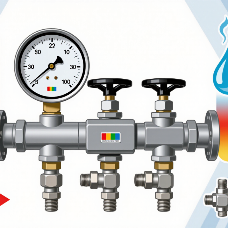
Define the Role and Operating Conditions of a Single Gauge Manifold
Choosing a single gauge manifold in 2026 starts with its role, not its appearance. Decide whether it will measure pressure, isolate a line, or support calibration work. A manifold used beside a compressor faces vibration, heat, oil mist, and frequent connection changes. A panel-mounted unit may need compact ports, clear readings, and stable mounting. Define the medium, pressure range, temperature, connection size, and expected cycling before comparing materials. Field technicians often find that a suitable pressure range still fails when the seal material does not suit the process.
Tips: Write the operating conditions on one page. Include normal pressure, maximum pressure, ambient temperature, fluid compatibility, and maintenance access. Check whether the gauge can be read from the operator’s position. Leave room for a wrench and protective cap. Ask for calibration records and pressure-test evidence from the supplier. These documents do not replace inspection, but they make decisions more traceable. A small oversight remains possible.
For dependable selection, match the manifold’s isolation function to the work sequence. A two-valve layout may serve simple measurement, while a three-valve arrangement can support isolation and controlled equalization. Never treat the valve count as a quality rating. Verify port orientation, flow direction, vent location, and the required pressure class. During commissioning, open valves gradually and check for leakage around every joint. Record the initial reading and repeat it after the system reaches operating temperature. Real installations are less tidy than drawings. Leave space for that reality.
How to Choose a Single Gauge Manifold in 2026? - Define the Role and Operating Conditions of a Single Gauge Manifold
| Selection Dimension | Recommended Definition | Typical Data or Operating Range | Why It Matters |
|---|---|---|---|
| Primary Function | Use a two-valve single gauge manifold for pressure indication, instrument isolation, and controlled depressurization. | One process isolation valve plus one vent or bleed valve connected to a single pressure gauge. | This configuration allows the gauge to be isolated for inspection or replacement without shutting down the entire process, where the installation design permits it. |
| Pressure Range | Select a gauge and manifold whose maximum allowable working pressure exceeds the normal and abnormal pressure conditions of the system. | Common gauge scales include 0–1.6, 0–2.5, 0–4, 0–6, 0–10, 0–16, 0–25, and 0–40 bar; equivalent psi scales are also widely used. | For improved readability and reduced mechanical stress, normal operating pressure is commonly kept near the middle portion of the gauge scale rather than at the upper limit. |
| Pressure Class Verification | Confirm the pressure rating of the complete assembly, including the body, valves, fittings, tubing, seals, and gauge connection. | Do not treat a nominal connection size or thread type as a pressure rating. Ratings must be checked at the actual operating temperature. | The lowest-rated component determines the safe working limit of the assembled manifold system. |
| Process Temperature | Specify the minimum, normal, and maximum process and ambient temperatures. | Standard metallic manifolds are often used in ambient service around −20 °C to 80 °C, but the permitted range depends on the material, seal, gauge, and connection design. | Temperature can reduce seal performance, change material strength, and affect the pressure rating of the assembly. |
| Process Fluid Compatibility | Match all wetted materials with the process fluid, including the body, stem, seat, packing, gasket, and diaphragm or sensing element. | 316 or 316L stainless steel is widely selected for general industrial and many corrosive services. Nickel alloys or special materials may be required for highly aggressive media. | Material compatibility reduces corrosion, leakage, contamination, and premature failure. |
| Gas, Liquid, or Steam Service | Identify whether the manifold will handle gas, liquid, condensable vapor, steam, oxygen, or hazardous media. | Steam and hot vapor service may require a cooling leg, siphon, impulse line, or remote installation. Gas service may require leak-tight connections and controlled vent routing. | Fluid phase and temperature influence measurement accuracy, installation orientation, drainage, and operator safety. |
| Valve Arrangement | Use a straight-through block-and-bleed arrangement when one gauge requires isolation and venting. | A single gauge manifold normally has two functional valves: process isolation and vent or bleed. It does not provide transmitter equalization unless specifically designed for that purpose. | Choosing the correct valve arrangement prevents unnecessary complexity and avoids using a single gauge manifold for differential-pressure applications that require equalization. |
| Connection Type | Match the process and gauge connections to the piping specification and installation method. | Common options include NPT, BSPP, BSPT, tube compression connections, and flanged interfaces. Typical gauge ports include 1/4 or 1/2 nominal connections, subject to the design. | Correct thread form, size, sealing method, and engagement length are essential for mechanical integrity and leak prevention. |
| Seal and Packing Material | Select seals according to fluid chemistry, temperature, pressure, and emissions requirements. | Common choices include PTFE, graphite, elastomers, and metal seals. Oxygen, sour-gas, high-temperature, and vacuum services may require special cleaning or sealing specifications. | The wrong seal can swell, harden, permeate, decompose, or leak under service conditions. |
| Gauge Accuracy | Choose accuracy according to the monitoring, control, or safety function of the gauge. | Industrial gauges are commonly available with accuracy classes such as 0.5, 1.0, or 1.6 percent of span, depending on the gauge design and applicable standard. | Higher accuracy may be necessary for calibration, testing, or process control, while general indication may not require it. |
| Vibration and Pulsation | Assess pump pulsation, compressor vibration, water hammer, and pressure cycling before selecting the gauge and manifold. | Possible measures include a liquid-filled gauge, snubber, restrictor, pulsation dampener, remote mounting, or reinforced tubing arrangement. | Reducing pressure spikes and vibration improves gauge life, reading stability, and connection reliability. |
| Vent and Drain Direction | Orient the bleed outlet toward a safe collection point or a closed vent system. | For hazardous, toxic, flammable, or environmentally regulated media, use tubing or piping to route the discharge to an approved containment or recovery system. | A bleed valve must not discharge toward personnel, electrical equipment, walkways, or unprotected work areas. |
| Installation Orientation | Install the manifold and gauge in a position that supports readability, drainage, venting, and maintenance access. | Liquid lines are generally arranged to avoid unwanted gas pockets; gas lines are arranged to avoid liquid accumulation at the sensing point. Final orientation depends on the process and gauge design. | Correct orientation helps prevent measurement error, corrosion, freezing, and trapped pressure. |
| Applicable Standards | Specify the standards required by the project, industry, location, and pressure equipment regulations. | Relevant references may include ASME B40.100 for pressure gauges, ISO 5171 for pressure gauges, ASME B16.5 for applicable flanged interfaces, and ISO 15156/NACE MR0175 for selected sour-service materials. | Standards define requirements for materials, dimensions, testing, accuracy, and service suitability. The applicable edition and project specification should always be confirmed. |
| Testing and Documentation | Require pressure testing, leak testing, material traceability, and calibration documentation when the application demands it. | Typical records may include a hydrostatic or pneumatic test report, material certificate, gauge calibration certificate, and cleaning certificate for special services. | Documented verification supports commissioning, maintenance, audits, and safe replacement. |
| Safety and Maintenance | Provide a safe isolation and depressurization procedure before gauge removal or manifold maintenance. | Close the process isolation valve, verify zero pressure through the bleed path, and confirm that the vented fluid is safely contained before loosening any connection. | A closed isolation valve alone does not prove that the gauge connection is pressure-free. |
| When a Single Gauge Manifold Is Not Suitable | Use a different manifold configuration when the measurement requires more than simple gauge isolation and bleeding. | Differential-pressure transmitters generally require a three-valve or five-valve manifold. Multiple instruments may require separate isolation points or an engineered valve assembly. | Selecting a single gauge manifold for a multi-line or differential-pressure application can prevent proper equalization, calibration, and safe maintenance. |
Note: Pressure, temperature, material, and connection values are typical engineering selection references. Always verify the complete assembly rating against the actual process conditions, applicable standards, and site safety requirements.
