Choosing the right Jacquard Driving Board can determine whether a textile line runs smoothly or loses hours to unstable patterns and repeated adjustments. In practice, the board is not merely a control component. It coordinates electronic signals, needle selection, pattern accuracy, response speed, and communication with the loom system. A small mismatch may appear as broken motifs, uneven fabric, or unexplained machine stops.
Industry data supports careful selection. The International Textile Machinery Federation’s International Textile Machinery Shipment Statistics reports continued investment in modern weaving equipment, although demand differs across regions and machine categories. This shift increases the need for compatible, serviceable control hardware. Market reports from MarketsandMarkets also identify automation, digital control, and production efficiency as important directions in textile machinery. These reports offer useful context, but they do not replace testing the board on your actual loom.
Details matter. Check interface compatibility, output capacity, operating voltage, heat resistance, firmware support, and repair access. Ask how the board performs during long production runs, not only during a short demonstration. A supplier should provide wiring diagrams, test records, failure guidance, and traceable specifications. That evidence builds confidence.
Some choices still remain difficult. The cheapest board may reduce the purchase budget but increase downtime later. A high-end model may offer features your factory never uses. This guide presents ten practical tips for comparing a Jacquard Driving Board by reliability, integration, maintenance, and lifecycle value. Think beyond the first quotation. A stable signal at 2 a.m. can matter more than a polished sales brochure.
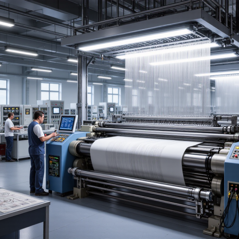
A Jacquard driving board controls how pattern data reaches the lifting mechanism. Its core work includes signal processing, actuator control, timing, and fault monitoring. Common types include electronic boards, modular boards, and servo-controlled boards. Electronic boards suit modern looms with digital pattern files. Modular designs help technicians replace one section without changing the entire system. Servo-controlled versions offer accurate movement and smoother speed adjustment, especially in complex patterns.
Tip 1: Match the board with the loom’s voltage, connector layout, and communication protocol. A perfect-looking board can still fail when timing signals differ.
Tip 2: Check driving capacity, including channel quantity, switching frequency, and heat tolerance. During factory testing, I inspect wiring temperature after long operation. Small heat marks often reveal overloaded circuits earlier than software alarms.
Core functions should include stable pulse output, synchronized shedding control, and protection against overcurrent or signal loss. Look for clear diagnostic indicators and accessible testing points. These details reduce downtime and make maintenance less dependent on guesswork.
Tip 3: Ask for waveform data, service records, and compatibility instructions before purchase. Technical documents are more useful than confident promises.
Tip 4: Consider future pattern expansion, not only today’s production needs. I once focused too much on initial cost; the limited interface later created unnecessary delays. A reliable choice balances response speed, repair access, operating conditions, and verified machine compatibility.
Match the board to your machine, not only to the pattern size.
Tip 1: Confirm the jacquard head type and hook count. Tip 2: Check the machine’s rated voltage, current, and connector pinout. Tip 3: Compare the board’s output channels with every solenoid group. A small mismatch can stop production. Tip 4: Verify mounting holes and board dimensions before ordering.
ITMF’s 46th International Textile Machinery Shipment Statistics reported about 119,000 shuttleless looms shipped in 2023, a 39% yearly decline. This pressure makes reliable upgrades more important.
Tip 5 Match the communication protocol and signal timing. Some machines require precise synchronization with the main shaft encoder. Tip 6 Check pattern memory and file compatibility.
Tip 7: Review the maximum operating speed under real load, not laboratory conditions. Tip 8: Inspect cooling space, dust protection, and cable length.
In factory trials, heat near the control cabinet often receives too little attention. That is a practical weakness.
Tip 9: Ask for wiring diagrams, test records, and firmware details. ISO 13849-1 also encourages risk-based evaluation of safety-related control systems.
Tip 10: Test one board on an idle machine before full installation. Record missed hooks, repeated faults, and temperature changes.
Do not trust a perfect first sample.
Textile floors contain vibration, lint, and unstable power. A second review may reveal what specifications alone miss.
10 Tips to Choose the Right Jacquard Driving Board
Evaluate the controller before judging its price. Tip 1: Confirm voltage, current, and connector compatibility with the existing loom. Tip 2: Check communication protocols and signal timing. Tip 3: Request a complete wiring diagram, not only a product photo. Tip 4: Test the board with your actual actuator load. A bench test is not enough. I once trusted matching connectors and missed a timing difference that caused irregular lifting. That mistake was avoidable.
Pattern programming deserves equal attention. Tip 5: Verify file formats, pattern capacity, and transfer methods. Tip 6: Ask whether the software supports editing, scaling, and repeat settings. Tip 7: Examine how easily operators can correct one row during production. Clear menus matter. Tip 8: Check memory protection and backup procedures. Losing a carefully prepared pattern wastes more than time. A small error matters.
Maintenance can reveal the board’s real value. Tip 9: Choose diagnostic tools that show sensor faults, communication errors, and channel status. Tip 10: Confirm technical documentation, training, and replacement support. Ask for test records under working conditions. Keep sample patterns ready for comparison. The best choice may still require adjustment after installation. Control compatibility and programming needs should be reviewed together, because a powerful board becomes limiting when operators cannot use it confidently.
| No. | Evaluation Dimension | What to Check | Practical Selection Guidance | Verification Method | Potential Risk if Mismatched |
|---|---|---|---|---|---|
| 1 | Machine and Harness Compatibility | Connector layout, pin assignment, output channel arrangement, signal polarity, and cable length. | Select a board whose electrical interface matches the existing machine wiring, or plan a documented harness conversion. | Compare the machine wiring diagram with the board pinout and perform a continuity test before applying power. | Incorrect wiring can cause inactive hooks, unintended actuation, short circuits, or permanent component damage. |
| 2 | Solenoid Capacity and Channel Count | Number of independently controlled hooks or needles, connector grouping, and spare output requirements. | Choose a channel count equal to or greater than the machine’s active actuators, including any required expansion margin. | Confirm the actual hook count and map every output channel to a physical actuator during a low-speed test. | Insufficient channels create missing pattern elements; incorrect channel mapping produces distorted designs. |
| 3 | Electrical Voltage and Current Handling | Required supply voltage, peak coil current, average load, protection against overcurrent, and heat dissipation. | Match the board to the solenoid electrical rating and verify that the power supply can support simultaneous or grouped activation. | Measure the supply under load and compare coil resistance and current requirements with the board specifications. | Voltage mismatch may cause weak actuation, overheating, driver failure, or shortened solenoid life. |
| 4 | Timing and Motion Synchronization | Clock input, encoder or position signal, firing delay, cycle speed, and synchronization with the main shaft. | Prefer adjustable timing and a position-feedback input when the machine operates at variable speed or requires precise shed formation. | Run a test pattern at several speeds and compare the programmed position with the actual fabric repeat. | Timing errors can create skipped picks, pattern displacement, uneven shed opening, or fabric defects. |
| 5 | Pattern Programming Format | Supported pattern file formats, bitmap or matrix structure, repeat size, color or lift coding, and data conversion rules. | Choose a controller that accepts the formats used by the design workflow and preserves the intended hook sequence without manual re-entry. | Import a representative production file and compare its row, column, repeat, and lift information with the source design. | Unsupported or incorrectly converted files may produce reversed, mirrored, truncated, or incomplete patterns. |
| 6 | Pattern Memory and Data Management | Internal memory, removable storage, maximum pattern size, file naming, backup, and recovery functions. | Allow enough capacity for the largest repeat and retain backup space for production recipes and revisions. | Load the largest planned pattern, save multiple revisions, and verify that data remains intact after restart. | Limited memory can force pattern segmentation, while poor data protection increases the risk of lost production settings. |
| 7 | Communication with the Main Controller | Communication interface, data rate, handshaking, start/stop signals, fault feedback, and electrical isolation. | Use an interface supported by the machine controller and confirm whether real-time synchronization or only pattern transfer is required. | Test start, stop, reset, fault, and data-transfer commands under normal and interrupted communication conditions. | Communication failure may stop production, desynchronize the pattern, or prevent the machine from responding safely. |
| 8 | Diagnostics and Fault Monitoring | Channel indicators, error codes, open-coil detection, short-circuit protection, event logs, and test mode. | Prioritize clear channel-level diagnostics when rapid troubleshooting and reduced downtime are important. | Disconnect one actuator at a time and confirm that the board identifies the correct channel and fault condition. | Poor diagnostics increase troubleshooting time and may allow repeated faults to damage drivers or solenoids. |
| 9 | Operating Environment and Reliability | Permitted temperature and humidity, vibration resistance, dust protection, cooling, grounding, and electrical noise tolerance. | Select an enclosure and installation method suited to the loom area, with adequate airflow and protection from lint, moisture, and vibration. | Review environmental ratings and monitor board temperature during a continuous production trial. | Heat, dust, moisture, or electromagnetic interference can cause intermittent outputs and premature electronic failure. |
| 10 | Safety, Maintenance, and Lifecycle Support | Emergency-stop behavior, safe restart, isolation, replaceable modules, firmware update process, documentation, and spare availability. | Choose a board with documented fail-safe behavior, accessible maintenance procedures, and support for the expected service period. | Test emergency stop, power recovery, fault reset, firmware backup, and replacement-board configuration before production use. | Unsafe restart or unavailable spare parts can increase injury risk, downtime, and total ownership cost. |
Choosing the right jacquard driving board requires more than checking output channels. Durability starts with the operating environment. Look for stable performance under vibration, heat, humidity, and repeated switching. IPC-A-610 workmanship criteria can help evaluate solder joints, connectors, and assembly quality. In textile production, dust is easily overlooked. It can settle inside cooling paths and raise component temperatures.
Maintenance should be practical, not theoretical. Ask whether technicians can replace fuses, connectors, or control modules without removing the entire loom interface. Uptime Institute’s 2024 Annual Outage Analysis reported that 54% of serious outages exceeded $100,000 in total impact. The figure concerns data facilities, but the lesson applies: small failures can create expensive downtime. Favor boards with visible diagnostics, fault logs, and clear wiring labels. Remote support helps. It is not a substitute for local skills.
Safety requires documented testing and disciplined installation. Check insulation protection, grounding, emergency-stop compatibility, and conformity with applicable machinery standards such as IEC 60204-1. A supplier should provide test records, firmware procedures, spare-part availability, and realistic response times. Request evidence, not promises. Manufacturing surveys often show maintenance teams struggle with skills shortages, so unclear manuals create risk. I would also test one board during normal production before wider adoption. Laboratory results can be excellent, yet field behavior may differ. That uncomfortable gap deserves attention.
10 Tips to Choose the Right Jacquard Driving Board
A low purchase price rarely shows the complete cost. Compare the board, compatible cables, control software, shipping, spare parts, and technician time. Ask for a written warranty and a clear test report. Reliable suppliers should explain failure rates, inspection methods, and replacement procedures without vague promises.
Measure the installation area before ordering. Check mounting holes, board dimensions, voltage, current, grounding, cooling, and communication compatibility. A crowded cabinet can trap heat around the driving board. Leave service space for probes, connectors, and safe cable handling. Confirm whether your existing jacquard machine needs adapters or firmware changes. Installation may require a qualified technician, especially when power loads are high.
Long-term value depends on stability, repair access, and energy use. Review the expected operating hours, working temperature, dust exposure, and vibration level. Choose components that can be replaced individually rather than discarding an entire assembly. Ask how long technical support and software updates will remain available. In my experience, a slightly higher initial cost can reduce repeated stoppages and emergency labor. Still, this is not guaranteed. One project underestimated cable routing and lost two production days. A small pilot installation could have revealed that problem earlier. Calculate total cost over three to five years, including downtime, inspections, electricity, and training. Keep installation drawings and test records. They make future troubleshooting faster.
Fill out the form below and our team will get back to you ASAP.
Snake Tray® is Green and Proudly Powered by the Sun! Snake Tray is committed to designing and manufacturing products that have many green benefits. Our products are made of recycled goods, minimize material waste, are energy efficient, use less non-renewable resources and nest together read more…
Snake Tray® 291 Skip Lane, Bay Shore NY 11706 | PHONE: 631-674-0004 | FAX: 631-674-0010 | www.bakoselectric.com | LEGAL | MADE IN USA
© 2025 SnakeTray. All rights reserved
Fill out the form below to download your document.